
Utility-scale PV design directly on CAD.
Analyze the terrain, optimize the layout and generate fully editable technical designs in AutoCAD, Civil 3D and ZWCAD.
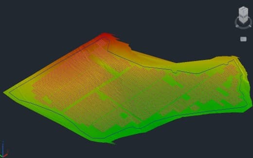
Generates a precise topographic surface at the contour interval you define.
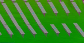
Define azimuth, pitch, corridors and setbacks to generate each tracker in 3D.
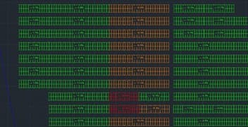
Checks the distance to the terrain and automatically flags potential violations.
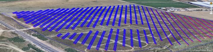
Export the design to KML/KMZ and view it at its real-world location.
01 — SPEED
Faster designs
Automates repetitive tasks and speeds up early-stage engineering.
02 — ACCURACY
Real topography
Design with real slopes, clearance and site constraints.
03 — CONTROL
Fully editable CAD
Modify the layout without losing traceability or flexibility.
04 — CONTINUITY
Technical export
Continue the work in DWG, CSV, KML/KMZ and PVsyst.
From terrain to finished project, without leaving CAD.
Discover how PVLTRA connects topographic analysis, plant design and engineering preparation within a single editable workspace.
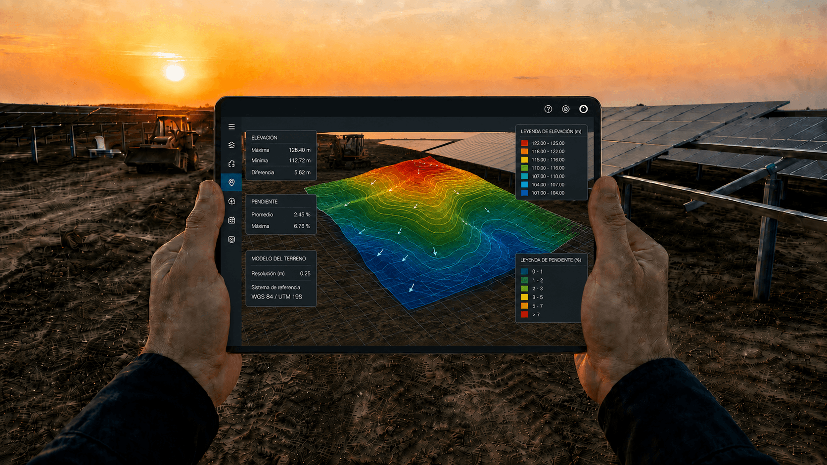
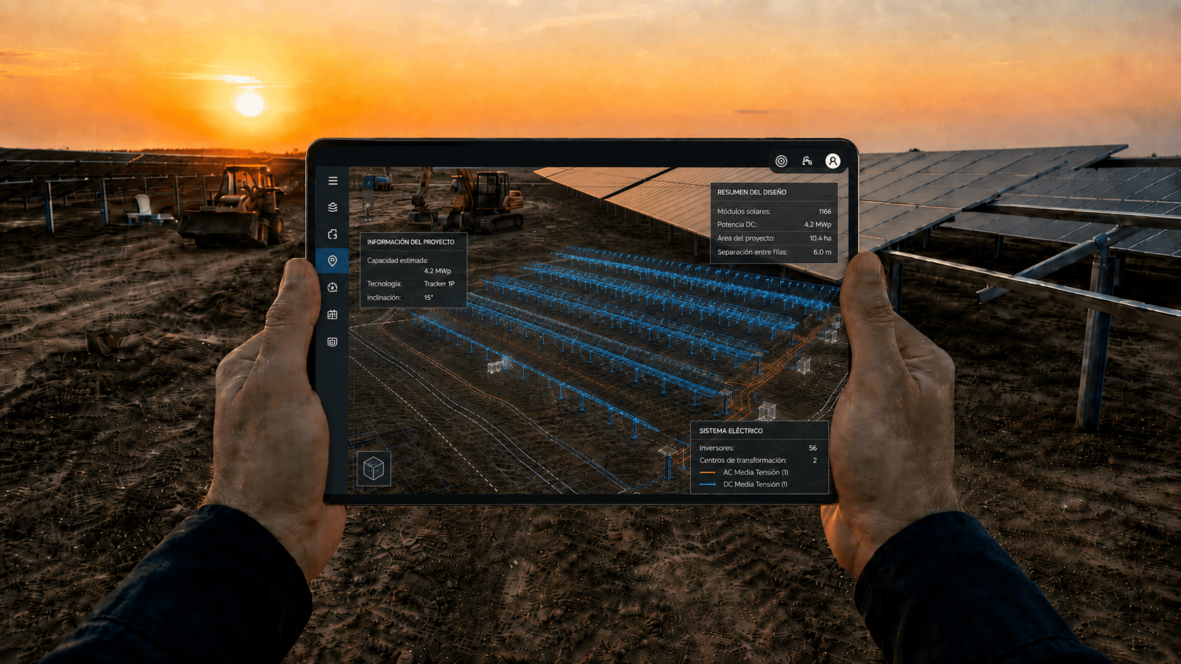
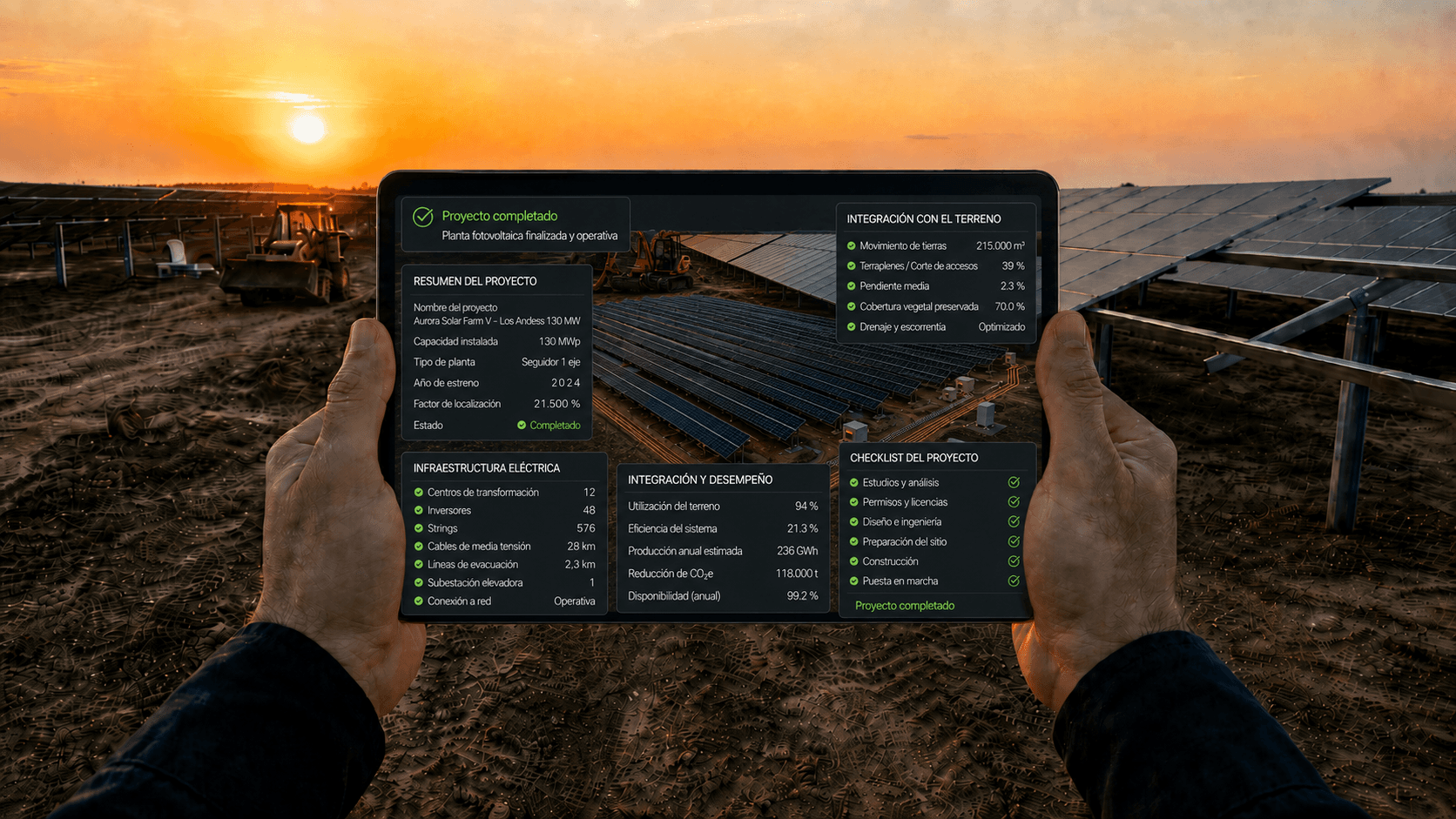
Analyze the terrain
Topographic analysis
Turns real topography into an editable design surface.
Analyze the terrain
Topographic analysis
Turns real topography into an editable design surface.
A CAD-first workflow to design with more control.
Design on CAD
Geometry lives inside AutoCAD, Civil 3D or ZWCAD. No intermediate exports, no model duplication.
Terrain and civil analysis
TIN surfaces, slope analysis, cut/fill and earthworks with editable criteria.
Technical exports
Structured DWG, CSV for piles and trackers, inputs for PVsyst and BoM ready for EPCs.
A modular ecosystem to design photovoltaic plants on CAD.
Enable only the features required for each project: terrain, layout, structures, civil works, electrical, validation and export working as a single connected flow.
PV layout
Automatic distribution of tables, trackers and implantation zones with clearance, corridor, restriction rules and editable CAD geometry.
AvailableTerrain and slopes
TIN surface analysis, contour lines, longitudinal and transversal slopes to make design decisions from real topography.
AvailableEarthworks
Cut and fill computation, surface comparison and per-zone metrics to optimize grading and control volumes.
AvailableStructures and trackers
Design of fixed structures and 2D/3D trackers with editable parameters, pitch, clearance, piles and terrain adaptation.
AvailablePiles and stakeout
Management of pile lengths, positions and coordinates per row, with exports ready for construction and site control.
AvailableElectrical module
DC/AC routing, trenches, assignment of structures to inverters and transformer stations with smart tagging.
AvailableValidation and QA
Checking tools for collisions, slopes, clearance, 3D geometry, tags, zone metrics and model consistency.
AvailableProfessional exports
Outputs for PVsyst, KML/KMZ, CSV, tables, profiles, coordinates and technical documentation connected directly to the CAD design.
AvailableCAD productivity
Contextual utilities to edit tags, calculate power and areas, link texts, swap structures and speed up repetitive tasks.
AvailableEverything you need to know about PVLTRA.
Find answers to the most common questions about the platform, how it works inside CAD, and how it applies to utility-scale PV plant design.
PVLTRA is a design platform for utility-scale photovoltaic plants that works directly inside the CAD environment. It connects terrain analysis, layout generation and engineering preparation in a single editable workflow.
It is designed for engineering firms, EPCs, developers, manufacturers and technical teams who design or evaluate large-scale PV plants and need to speed up their work without losing control over geometry and results.
PVLTRA is currently compatible with AutoCAD, Civil 3D and ZWCAD. Compatibility with BricsCAD is planned for the near future.
No. PVLTRA installs and works inside the CAD environment itself. Users can analyze the terrain, generate the layout, review results and modify the design without switching platforms or rebuilding the geometry afterward.
Yes. Elements generated by PVLTRA remain visible and editable inside the CAD drawing. The engineering team can modify structures, corridors, clearances, perimeters and other parameters without depending on a closed result or a black box.
PVLTRA lets you create and use TIN surfaces, generate contour lines, analyze slopes and study how topography shapes the design. It also helps identify unsuitable zones or areas that may require layout adjustments or earthworks.
Yes. The platform can check the distance of the modules relative to the terrain and help detect potential non-compliance through visual results and color coding.
Yes. PVLTRA lets you analyze terrain adaptation solutions, including cuts, fills, smoothing and generation of design surfaces according to the technical criteria defined for the project.
Yes. PVLTRA lets you prepare and export technical information in formats such as DWG, CSV and KML/KMZ, as well as generate data to continue analysis and development in PVsyst.
No. It can be used to generate initial alternatives, analyze terrain feasibility, optimize the layout and advance engineering preparation and deliverables, keeping the model editable throughout the process.
You can request a demo with our team. We will briefly review your current workflow and show you in practice how PVLTRA can be applied to your projects and CAD tools.
Adapted to how each team works.
Engineering firms
Detailed technical design with traceability and editable criteria.
- Native TIN surfaces
- Slopes and earthworks
- EPC-ready exports
EPCs
From design to execution with consistent data.
- Piles and trackers CSV
- Automated BoM
- Geometry validations
Developers
Feasibility studies and fast pre-design on real topography.
- Installable capacity per plot
- Average slope analyzed
- Preliminary layout simulation
Installed inside your CAD, no external dependencies.
PVLTRA integrates as a native plugin. Geometry stays in your working environment.

AutoCAD
Available
Civil 3D
Available
ZWCAD
Available
BricsCAD
Coming soonReal impact on real projects.
−40%
Manual iterations
Fewer back-and-forths between topography, layout and civil.
×3
Pre-design speed
Faster feasibility studies on real topography.
100%
Editable geometry
The project lives in CAD, not in a closed format.
Estimated results depending on project type and the team's current workflow.
Designed for professional environments.
Controlled licensing, Azure infrastructure and data protection aligned with professional standards.
Per-user licensing
Manage additions, removals and extensions from a centralized portal.
Azure infrastructure
Services deployed on Azure with encryption in transit and at rest.
Project data
Geometry stays in the client's CAD. PVLTRA does not store designs in the cloud.
Compliance
Aligned with GDPR. Processing records available upon request.
Ready to work on real topography?
Request a technical demo and we will show you PVLTRA on a typical industry project.